
Wiki article · Collection 02
ZVS
Engineering reference on ZVS for wireless power system design, integration, and deployment.
6 minArticle 13/16Resonant WPT
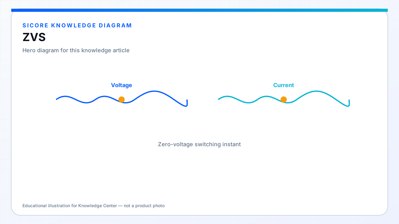
Zero-voltage switching (ZVS) turns a device on only after its voltage has rung to (near) zero, typically after the complementary device turns off and tank current charges/discharges the switch node capacitance through the body diode or channel.
01Conditions for ZVS
- Enough inductive current during the dead time to slew the switch-node capacitance.
- Dead time long enough to finish the transition, short enough to limit diode conduction loss.
- Operating point on the correct side of resonance for the chosen modulation scheme.
02Failure modes
Light load, detuned tanks, or an aggressive frequency jump can drop tank current and lose ZVS — sudden heating and EMI spikes follow. Protection and control should detect hard-switching regions and back out (power limit, frequency retreat, or shutdown) rather than silently cooking the bridge.